9.1 UB sections and UC sections: bearing, buckling and shear capacities for unstiffened webs
Values have been calculated as follows:
(a) Bearing
4.5.2.1
The bearing capacity Pw, of the unstiffened web is given by:
| Pw |
= (b1 + n k) t pyw |
(BS 5950-1 notation) |
| |
= b1C2 + C1 |
(Capacity table notation) |
where:
4.5.2.1
| b1 |
is the stiff bearing length |
| n |
= 5, for continuous over bearing |
| |
= 2 + 0.6 be / k , for end bearing |
| |
= 2, for end bearing (be taken as zero in the tables) |
| be |
is the distance to the nearer end of the member from the end of the stiff bearing |
| k |
= (T + r) for rolled sections |
| t |
is the thickness of the web |
| T |
is the thickness of the flange |
| r |
is the root radius |
| pyw |
is the design strength of the web. |
(i) Bearing factor C1 is due to the beam alone
| Generally, |
C1 = n k t pyw. |
|
| |
 C1 = 5 (T + r) t pyw C1 = 5 (T + r) t pyw |
for continuous over bearing |
| |
C1 = 2 (T + r) t pyw |
for end bearing. |
(ii) Bearing factor C2 is equal to t pyw and must be multiplied by b1 to give the stiff bearing contribution.
(b) Buckling
4.5.3.1
Generally the buckling resistance, Px, of the unstiffened web is given by:
Px =
K
Combining with (a), this can be re-written as:
4.5.3.1
| Px |
= K |
(BS 5950-1 notation) |
| |
= K (C4 Pw )0.5 |
(Capacity table notation) |
| if ae ≥ 0.7d |
then K = 1 |
| if ae < 0.7d |
then K =  |
where:
| d |
is the depth between fillets |
| t |
is the web thickness |
| Pw |
is the web bearing capacity from (a) above. |
| ae |
is the distance from the centre of the load or reaction to the nearer end of the member. |
(i) Buckling factor C4 is the same for end bearing and continuous over bearing,
C4 =

(c) Shear
The shear capacity of the section is given by:
Pv = 0.6 py t D
4.2.3
where:
| D |
= Total depth of section. |
Note: Since none of the rolled sections have d/t > 70ε, there is no need to check for shear buckling of the web.
9.2 Parallel flange channels: bearing, buckling and shear capacities for unstiffened webs
The nominal cross-section dimensions of parallel flange channels give a square heel, but the tolerances include a small heel radius (see Corus brochure Structural sections[11]), based on BS EN 10279:2000[7]. The heel radius can be between zero and 0.3 times the flange thickness.
In most cases the loads and reactions are applied directly to the web (by angle cleats, end plates or fin plates), so this is usually of no significance. However, if a force from a load or reaction is applied to the channel through the flange, the presence of a heel radius may produce eccentricity of this force relative to the web, so reduction factors, Kb for bearing and Kw for buckling to allow for this have been included in the tables.
The use of these reduction factors will provide acceptable design, but if necessary the eccentricity can be eliminated. A simple method is to use a continuously welded flange plate local to the stiff bearing, extending at least to the back of the channel. Depending on details, other methods may be appropriate.
Values have been calculated as follows:
(a) Bearing capacity, Pw
| Pw |
= Kb (b1 + nk)tpyw |
(BS 5950-1 notation) |
| |
= Kb (b1 C2 + C1) |
(Capacity table notation) |
Where
| Kb |
is a reduction factor to allow for heel radius. |
| All other notation as in Section 9.1. |
(b) Buckling resistance, Px
| Px |
= Kw |
(BS 5950-1 notation) |
| |
= Kw K (C4 PW)0.5 |
(Capacity table notation) |
where
| Kw |
is a reduction factor to allow for heel radius. |
| All other notation as in Section 9.1. |
4.2.3
(c) Shear capacity
Pv = 0.6 py t D
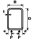
9.3 Square and rectangular hollow sections: bearing, buckling and shear capacities for unstiffened webs
Values have been calculated as follows:
(a) Bearing
4.5.2.1
The bearing capacity, PW, of the unstiffened web is given by:
| Pw |
= (b1 + nk)2t pyw |
(BS 5950-1 notation) |
| |
= b1C2 + C1 |
(Capacity table notation) |
where:
| b1 |
is the stiff bearing length (see figures below) |
| n |
= 5, for continuous over bearing |
| |
= 2, for end bearing |
| k |
= t, for hollow sections |
| t |
is the thickness of the web |
| pyw |
is the design strength of the web. |
Figure illustrating examples of stiff bearing length, b1
(i) Bearing factor C1 is due to the beam alone, for both webs.
| Generally, |
C1 = 2 n k t pyw |
|
| |
C1 = 2 x 5 t2 pyw |
for continuous over bearing |
| |
C1 = 2 x 2 t2 pyw |
for end bearing |
(ii) Bearing factor C2 is equal to 2tpyw for both webs and must be multiplied by b1 to give the stiff bearing contribution.
(b) Buckling
4.5.3.1
The buckling resistance Px of the two unstiffened webs is given by:
| Px |
= (b1 + n1) 2 t pc |
(BS 5950-1 notation) But, not given in code. |
| |
= b1C2 + C1 |
(Capacity table notation) |
where:
Table 24
Annex C.2
| b1 |
is the stiff bearing length |
| n1 |
is the length obtained by dispersion at 45° through half the depth of the section |
| t |
is the wall thickness |
| pc |
is the compressive strength based on:
- Web slenderness, λ =

- Strut curve (c).
|
Unless loads or reactions are applied through welded flange plates, the additional effects of moments in the web due to eccentric loading must be taken into account, which will result in lower buckling values.
(i) Buckling factor C1 is the portion of (n1 t pc) due to the beam alone.
| C1 = 4D t pc / 2 |
for welded flange plates |
| C1 = 4P |
for non‑welded flange plates |
where:
| P |
is the limiting force in each web (derived below). |
The factor 4 allows for two webs and dispersion of load in two directions and applies to a member that is continuous over bearing or an end bearing member with a continuously welded sealing plate.
For non‑welded flange plates, the equivalent eccentricity of loading from the centreline of the web is given by:
e = 0.026B + 0.978t + 0.002D
This expression has been derived from research [14] and is also applicable to cold‑formed hollow sections [15]
The loading P creates a fixed end moment of
M =

and thus the moment at the centreline of the web can be found as follows [16]:
My =

where:
Using the interaction expression 
The limiting value of P is given by substituting for My and rearranging:
P =
(ii) Buckling factor C2 is the stiff bearing component factor and is equal to C1/D and must be multiplied by b1 to give the stiff bearing contribution.
(c) Shear
4.2.3
The shear resistance capacity of the section is given by:
Pv = 0.6 py A D / (D + B)
where:
| A |
is the cross‑sectional area. |


