3.1General
All section properties have been accurately calculated and rounded to three significant figures. They have been calculated from the metric dimensions given in the appropriate standards (see Section 1.1). For angles, BS EN 10056-1 assumes that the toe radius equals half the root radius.
3.2Sections other than hollow sections
3.2.1Second moment of area (I )
The second moment of area has been calculated taking into account all tapers, radii and fillets of the sections. Values are given about both the y-y and z-z axes.
3.2.2Radius of gyration (i )
The radius of gyration is a parameter used in the calculation of buckling resistance and is derived as follows:
i = [I / A]1/2
where:
| I |
is the second moment of area about the relevant axis |
| A |
is the area of the cross section. |
3.2.3Elastic section modulus (Wel )
The elastic section modulus is used to calculate the elastic design resistance for bending or to calculate the stress at the extreme fibre of the section due to a moment. It is derived as follows:
| Wel,y = Iy / z |
| Wel,z = Iz / y |
where:
| z, y |
are the distances to the extreme fibres of the section from the elastic y-y and z-z axes, respectively. |
For parallel flange channels, the elastic section modulus about the minor (z-z) axis is given for the extreme fibre at the toe of the section only.
For angles, the elastic section moduli about both axes are given for the extreme fibres at the toes of the section only. For elastic section moduli about the principal axes u-u and v-v, see AD340[16].
3.2.4Plastic section modulus (Wpl )
The plastic section moduli about both y-y and z-z axes are tabulated for all sections except angle sections.
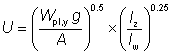
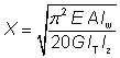
3.2.5Buckling parameter (U ) and torsional index (X )
UB sections, UC sections and parallel flange channels
The buckling parameter (U ) and torsional index (X ) have been calculated using expressions in Seelbiz document SN002: Determination of non-dimensional slenderness of I and H sections[22].
where:
| Wpl,y |
is the plastic modulus about the major axis |
| g |
=  |
| Iy |
is the second moment of area about the major axis |
| Iz |
is the second moment of area about the minor axis |
| E |
= 210 000 N/mm2 is the modulus of elasticity |
| G |
is the shear modulus where  |
| ν |
is Poisson’s ratio (= 0.3) |
| A |
is the cross–sectional area |
| Iw |
is the warping constant |
| IT |
is the torsional constant. |
Tee sections
The buckling parameter (U ) and the torsional index (X ) have been calculated using the following expressions:
| U = [(4 Wpl,y2 g2 / (A2 h2)]1/4 |
| X = 0.566 h [A/ IT]1/2 |
where:
| Wpl,y |
is the plastic modulus about the major axis |
| g |
= |
| Iy |
is the second moment of area about the major axis |
| Iz |
is the second moment of area about the minor axis |
| A |
is the cross–sectional area |
| h |
is the distance between shear centres of flanges (for T sections, h is the distance between the shear centre of the flange and the toe of the web) |
| IT |
is the torsional constant. |
3.2.6Warping constant (Iw ) and torsional constant (IT )
Rolled I sections
The warping constant and St Venant torsional constant for rolled I sections have been calculated using the formulae given in the SCI publication P057 Design of members subject to combined bending and torsion[12].
In Eurocode 3 terminology, these formulae are as follows:
Iw =  |
where:
| Iz |
is the second moment of area about the minor axis |
| hs |
is the distance between shear centres of flanges (i.e. hs = h – tf) |
| IT |
= 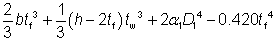 |
where:
| α1 |
= – 0.042 + 0.2204  + 0.1355 + 0.1355  – 0.0865 – 0.0865  – 0.0725 – 0.0725  |
| D1 |
=  |
| b |
is the width of the section |
| h |
is the depth of the section |
| tf |
is the flange thickness |
| tw |
is the web thickness |
| r |
is the root radius. |
Tee sections
For Tee sections cut from UB and UC sections, the warping constant (Iw) and torsional constant (IT) have been derived as given below.
Iw = 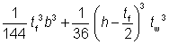 |
IT = 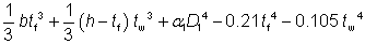 |
where:
| α1 |
= – 0.042 + 0.2204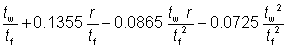 |
| D1 |
is as defined above |
Note: These formulae do not apply to tee sections cut from joists, which have tapered flanges. For such sections, expressions are given in SCI Publication P057[12].
Parallel flange channels
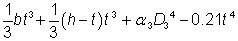
For parallel flange channels, the warping constant (Iw) and torsional constant (IT) have been calculated as follows:
Iw = 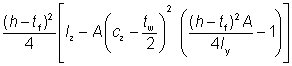 |
IT = 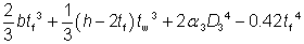 |
where:
| cz |
is the distance from the back of the web to the centroidal axis |
| α3 |
=  |
| D3 |
=  |
Note: The formula for the torsional constant (IT) is applicable to parallel flange channels only and does not apply to tapered flange channels.
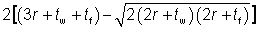
Angles
For angles, the torsional constant (IT) is calculated as follows:
IT =
where:
| α3 |
= 0.0768 +0.0479  |
| D3 |
=  |
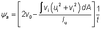
3.2.7Equivalent slenderness coefficient (ϕ ) and monosymmetry index (y )
Angles
The buckling resistance moments for angles have not been included in the bending resistance tables of this website as angles are predominantly used in compression and tension only. Where the designer wishes to use an angle section in bending, BS EN 1993-1-1, 6.3.2 enables the buckling resistance moment for angles to be determined. The procedure is quite involved.
As an alternative to the procedure in BS EN 1993-1-1, supplementary section properties have been included for angle sections in this website which enable the designer to adopt a much simplified method for determining the buckling resistance moment. The method is based on that given in BS 5950-1:2000 Annex B.2.9 and makes use of the equivalent slenderness coefficient and the monosymmetry index.
The equivalent slenderness coefficient (ϕa) is tabulated for both equal and unequal angles. Two values of the equivalent slenderness coefficient are given for each unequal angle. The larger value is based on the major axis elastic section modulus (Wel,u) to the toe of the short leg and the lower value is based on the major axis elastic section modulus to the toe of the long leg.
The equivalent slenderness coefficient (ϕa) is calculated as follows:
ϕa =

where:
| Wel,u |
is the elastic section modulus about the major axis u-u |
| g |
=  |
| Iv |
is the second moment of area about the minor axis |
| Iu |
is the second moment of area about the major axis |
| A |
is the area of the cross section |
| IT |
is the torsional constant. |
The monosymmetry index (ψa) is calculated as follows:
where:
| ui and vi |
are the coordinates of an element of the cross section |
| v0 |
is the coordinate of the shear centre along the v-v axis, relative to the centroid |
| t |
is the thickness of the angle. |
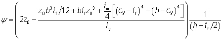
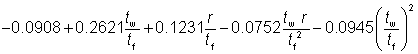
Tee sections
The monosymmetry index is tabulated for Tee sections cut from UBs and UCs. It has been calculated as:
where:
| z0 |
= Cy - tf /2 |
| Cy |
is the distance from the outside of the flange to the centroid of the section (measured parallel with the web) |
| b |
is the flange width |
| tf |
is the flange thickness |
| tw |
is the web thickness |
| h |
is the depth of the section. |
The above expression is based on BS 5950-1, Annex B.2.8.2.
3.3Hollow sections
Section properties are given for both hot-finished and cold-formed hollow sections (but not for cold-formed elliptical hollow sections). For the same overall dimensions and wall thickness, the section properties for square and rectangular hot-finished and cold-formed sections are different because the corner radii are different.
3.3.1Common properties
For general comment on second moment of area, radius of gyration, elastic and plastic modulus, see Sections 3.2.1, 3.2.2, 3.2.3 and 3.2.4.
For hot-finished square and rectangular hollow sections, the section properties have been calculated using corner radii of 1.5t externally and 1.0t internally, as specified by BS EN 10210-2[8].
For cold-formed square and rectangular hollow sections, the section properties have been calculated using the external corner radii of 2t if t ≤ 6 mm, 2.5t if 6 mm < t ≤ 10 mm and 3t if t > 10 mm, as specified by BS EN 10219-2[9]. The internal corner radii used are 1.0t if t ≤ 6 mm, 1.5t if 6 mm < t £ 10 mm and 2t if t > 10 mm, as specified by BS EN 10219-2[9].
3.3.2Plastic section modulus of hollow sections (Wpl )
The plastic section moduli (Wpl) about both principal axes are given in the tables.
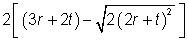
3.3.3Torsional constant (IT )
For circular hollow sections:
For square, rectangular and elliptical hollow sections:
IT =  |
where:
| I |
is the second moment of area of a CHS |
| t |
is the thickness of the section |
| p |
is the mean perimeter length |
| |
For square and rectangular hollow sections: |
p = 2 [(b – t) + (h – t)] – 2 Rc (4 - π) |
| |
For elliptical hollow sections: |
p = 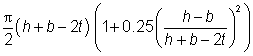 |
| Ap |
is the area enclosed by the mean perimeter |
| |
For square and rectangular hollow sections: |
Ap = (b – t) (h – t) – Rc2 (4 - π) |
| |
For elliptical hollow sections: |
Ap = 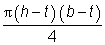 |
| Rc |
is the average of the internal and external corner radii |
3.3.4Torsional section modulus (Wt )
| Wt = 2Wel |
for circular hollow sections |
Wt =  |
for square, rectangular and elliptical hollow sections |
where:
| Wel |
is the elastic modulus and IT, t, Ap and p are as defined in Section 3.3.3. |