8.1 Bending: UB sections, UC sections and parallel flange channels
6.2.5 (2)
6.2.8 (2)
(a) Design resistance of cross section
The design resistances for bending about the principal axes of the cross section are given by:
(i) For Class 1, 2 cross sections:
(ii) For Class 3 cross sections with a Class 1 or 2 flange:
where Wpl,eff,y is calculated according to BS EN 1993-1-5, 4.4.
(iii) For other Class 3 cross sections:
(iv) For Class 4 cross sections:
Notes:
- None of the universal beams, universal columns or parallel flange channels in grade S275 or S355 are Class 4 under bending alone.
6.2.8 (3)
- Where the design shear force is high (> 50% of the shear resistance), a reduced value of resistance for bending Mv,y,Rd and Mv,z,Rd should be calculated. No values are tabulated in this website. Values of the design shear resistance Vc,Rd are given in the tables of web bearing and buckling resistance (see Section 9.1).
6.3.2
(b) Design lateral torsional buckling resistance moment
The lateral torsional buckling resistance moment Mb,Rd is given in the tables for a range of values of the following parameters:
- The length between lateral restraints, L, given at the head of the tables
- The value of factor C1
6.3.2.1 (3)
The lateral torsional buckling resistance moment, Mb,Rd, is given by:
where:
| Wy |
= Wpl,y |
for Class 1, 2 cross sections |
| Wy |
= Wpl,eff,y |
for Class 3 cross sections with Class 1 or 2 flanges |
| Wy |
= Wel,y |
for other Class 3 cross sections |
| Wy |
= Weff,y |
for Class 4 cross sections |
| ΧLT |
is the reduction factor for lateral–torsional buckling. It depends on the non‑dimensional slenderness  and the imperfection factor corresponding to the appropriate buckling curve. and the imperfection factor corresponding to the appropriate buckling curve. |
|
Mcr
|
is the elastic critical moment for lateral–torsional buckling based on gross section properties and takes into account the following:
- the moment distribution
- the length between lateral restraints.
=  |
| C1 |
is a factor that takes into account the shape of the bending moment diagram. Values of C1 given in the tables include 1.0; 1.13; 1.35; 1.5; 1.77; 2.0 and 2.5. Steelbiz document SN003 Elastic critical moment for lateral torsional buckling[24] gives background information related to this factor. To take C1 = 1,0 is conservative. |
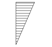
The C1 values of 1.13, 1.35 and 1.77 correspond to common design situations, as shown below.
| Loading |
Bending moment diagram |
C1 factor |
| UDL, pin-ended beam |
 |
1.13 |
| Central point load, pin-ended beam |
 |
1.35 |
| Triangular bending moment diagram, pin at one end |
 |
1.77 |
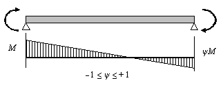
For linear bending moment diagrams, C1 may be determined from the following table, based on ψ, the ratio of the end moments.
| End moment loading |
y |
C1 |
 |
+1.00
+0.75
+0.50
+0.25
0.00
-0.25
-0.50
-0.75
-1.00
|
1.00
1.17
1.36
1.56
1.77
2.00
2.24
2.49
2.76
|
For other shapes of bending moment diagram, the factor C1 may be determined from the ratio:
Mcr may be determined by using the software LTBeam, freely available from www.cticm.com
6.3.2.3 (1)
The reduction factor ΧLT is calculated for the 'rolled sections' case, using buckling curves 'b' or 'c' as appropriate and the values of  and β given by the National Annex. The UK National Annex gives the following values:
 |
= 0.4 |
| β |
= 0.75 |
6.3.2.3(2) and the UK NA
The reduction factor is modified to take account of the moment distribution between the lateral restraints of members using the modification factor f:
 |
=  |
but |
 |
and |
 |
| f |
= |
but |
f ≤ 1.0 |
| kc |
=  |
8.2 Bending: Hollow sections
8.2.1 Circular and square hollow sections
The design resistances for bending Mc,Rd and the design shear resistance Vc,Rd are tabulated for circular and square hollow sections in S355 and S420 steel. No values have been calculated for S275 circular and square hollow sections. Mc,Rd has been calculated as detailed in Section 8.1 (a) above.
6.2.6 (2)
Vc,Rd is given by:
6.2.6 (3)
where:
| Av |
is the shear area |
| |
For circular hollow sections |
Av = 2A/π |
| |
For square hollow sections |
Av = A/2 |
| fy |
is the yield strength |
| γM0 |
is the partial factor for resistance of cross sections (γM0 = 1.0 as given in the National Annex). |
The second moment of area (I) is included in the tables because it is required for deflection checks.
For Class 4 CHS, BS EN 1993-1-4 refers the user to BS EN 1993-1-6. Moment resistance values for these sections have not been calculated and the symbol $ is shown instead.
8.2.2 Rectangular hollow sections
The following information is presented in the tables for rectangular hollow sections in S355 and S420 steel. No values have been calculated for S275 rectangular hollow sections.
(i) Design resistance for bending about the y-y and z-z axes and design shear resistance:
The values of Mc,y,Rd and Mc,z,Rd and Vc,Rd have been calculated as detailed in Section 8.1 (a) and Section 8.2.1 respectively, with the shear area for bending about the major axis taken as Av = A h / (b + h)
(ii) The section classification given in the tables applies to members subject to bending only about the appropriate axes. Sections may be Class 4 for pure bending about the y‑y or z‑z axis. It should be noted that a section may be Class 4 when bending about the z‑z axis and not Class 4 when bending about the y‑y axis.
(iii) The limiting length, Lc, is the length above which the design buckling resistance moment is reduced below the cross-sectional resistance due to lateral torsional buckling. The value of the limiting length is that at which the slenderness  , which is the value of
  according to the UK National Annex.
The slenderness for lateral torsional buckling has been calculated as follows:
And for RHS the elastic critical buckling moment is:
From these expressions, conservatively assuming C1 = 1.0, the limiting length above which LTB needs to be checked can be derived as follows:
For lengths up to the limiting length, Mb,Rd is equal to Mc,y,Rd.
In the resistance tables for bending alone, no values of Mb,Rd are tabulated for lengths in excess of the limiting length. Values for lengths in excess of the limiting length are provided in the tables of combined bending and compression.
(iv) The second moment of area (I) is repeated in the tables as it is required for deflection checks.
8.2.3 Elliptical hollow sections
The following information is presented in the tables for hot rolled elliptical hollow sections in S355 steel. No values have been calculated for S275 or S420 elliptical hollow sections:
(i) Design resistance for bending about the y-y axis
For Class 1, 2 and 3 sections, the design resistances are calculated in accordance with Section 8.1.
(ii) Design resistance for bending about the z-z axis
For Class 1, 2 and 3 sections, the design resistances are calculated in accordance with Section 8.1.
For Class 4 sections, the design resistances are calculated as if the section were Class 3, using a reduced design strength such that the section remains Class 3.
The reduced design strength is taken as

where De,minor is the equivalent diameter for buckling about the minor axis and is given by:
De,minor = 
(iii) Design resistance for shear
The design resistance for shear in the major axis of the elliptical section is calculated in accordance with Section 8.2.1. For an elliptical section, the shear area Av is taken as:
(iv) Limiting length, Lc
The limiting length, Lc above which the design buckling resistance moment is reduced below the cross-sectional resistance due to lateral torsional buckling has been calculated in accordance with Section 8.2.2.


 and the imperfection factor corresponding to the appropriate buckling curve.


 and β given by the National Annex. The UK National Annex gives the following values:


 , which is the value of


