9.1 UB sections, UC sections and parallel flange channels
6.2.6 (1), (2)
(a) The design shear resistance
The design shear resistance Vc,Rd is given by:
where:
| Av |
is the shear area |
| |
for rolled I sections Av = A – 2btf + (tw + 2r) tf but not less than ηhwtw, |
| |
for parallel flange channels Av = A – 2btf + (tw + r) tf |
| fy |
is the yield strength |
| γM0 |
is the partial factor for resistance of cross sections (γM0 = 1.0 as given in the National Annex). |
EN 1993‑1‑5
6.2 (1)
(b) Design resistance to local buckling
The design resistance of an unstiffened web, FRd, to local buckling under transverse forces is given by:
where:
| fy |
is the yield strength |
| tw |
is the thickness of the web |
| Leff |
is the effective length for resistance to transverse force ( = χF ly ) |
| χF |
=  ≤ 1.0 ≤ 1.0 |
| ly |
is the effective loaded length |
| γM1 |
is the partial factor for resistance of members (γM1 = 1.0 as given in the National Annex) |
 |
= |
Figure 6.1
| Fcr |
=  |
| kF |
=  but kF ≤ 6 but kF ≤ 6 |
| hw |
is the depth between flanges = h – 2tf |
| ss |
is the length of stiff bearing (see figure 6.2 of BS EN 1993-1-5) |
| c |
is the distance from the end of the stiff bearing to the end of the section. |
The effective loaded length ly has been calculated as the least value given by the following three expressions:
ly1 =  |
Eq (6.10) |
ly2 =  |
Eq (6.11) |
ly3 =  |
Eq (6.12) |
where:
| le |
=  ≤ ss + c ≤ ss + c |
Eq (6.13) |
| m1 |
=  |
| m2 |
=  |
if  |
| m2 |
= 0 |
if  |
(Note that, at present, BS EN 1993-1-5, 6.5(3) erroneously refers to Equations 6.11, 6.12 and 6.13. This error is due to be corrected by CEN.)
EN 1993-1-5
6.1 (4)
Values of FRd have been calculated for two values of c, where c is the distance from the end of the member to the adjacent edge of the stiff bearing length, as shown in Figure 6.1 of EN 1993-1-5. The values are:
c = 0 for a stiff bearing positioned at the end of the section
c = clim for a stiff bearing positioned at a distance clim from the end of the section. This position represents the minimum value of c at which the maximum resistance of the web for a given stiff bearing length, ss is attained.
where:
For the case where the stiff bearing is positioned at an intermediate distance (i.e. c < clim) the resistance given for c = 0 is conservative.
9.2 Square and rectangular hollow sections
BS EN 1993-1-5 does not cover the resistance to transverse forces for hollow sections. Therefore in this website the approach previously presented in P202 Volume 1 Section properties member capacities[25] has been adopted and is presented below in terminology consistent with BS EN 1993-1-1.
(a) Bearing
The bearing resistance, FRd,bearing, of the unstiffened web may be calculated using the factors C1 and C2 in the tables, using:
| FRd,bearing |
= (b1 + nk)2t fy / γM0 |
| |
= b1C2 + C1 |
(Resistance table notation) |
where:
| b1 |
is the effective bearing length (see figures below) |
| n |
= 5, for continuous web over bearing |
| |
= 2, for end bearing |
| k |
= t, for hollow sections |
| t |
is the wall thickness |
| fy |
is the yield strength. |

Figure illustrating examples of stiff bearing length, b1
The bearing factor C1 represents the contribution from the flanges, adjacent to both webs, and is given by:
| C1 |
= 2 n k t fy / γM0 |
Generally |
| C1 |
= 2 x 5 t2 fy / γM0 |
For a section continuous over the bearing |
| C1 |
= 2 x 2 t2 fy / γM0 |
For end bearing |
The bearing factor C2 is equal to 2tfy / γM0 representing the stiff bearing contribution for both webs.
(b) Buckling resistance
The buckling resistance FRd,buckling of the two unstiffened webs is given by:
| FRd,buckling |
= (b1 + n1) 2 t χ fy /γM1 |
|
| |
=b1C2 + C1 |
(Resistance table notation) |
where:
| b1 |
is the stiff bearing length |
| n1 |
is the length obtained by dispersion at 45° through half the depth of the section |
| t |
is the wall thickness |
| χ |
is the reduction factor for buckling resistance, based on the slenderness  as given in Section 6.1 as given in Section 6.1 |
| fy |
is the yield strength of the hollow section. |
Unless loads or reactions are applied through welded flange plates, the additional effects of moments in the web due to eccentric loading must be taken into account, which will result in lower buckling values.
The buckling factor C2 is the stiff bearing component factor and is equal to C1/h
The buckling factor C1 is the portion of (n1 t χ fy /γM1) due to the beam alone.
| C1 |
= 4D t χ fy /2γM1 |
for welded flange plates |
| C1 |
= 4F |
for non–welded flange plates |
where:
| F |
is the limiting force in each web (derived below). |
The factor of 4 allows for two webs and dispersion of load in two directions and applies to a member that is continuous over a bearing or an end bearing member with a continuously welded sealing plate.
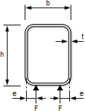
For non–welded flange plates, the limiting force F depends on the equivalent eccentricity of loading from the centreline of the web given by:
e = 0.026b + 0.978t + 0.002h
This expression has been derived from research[13] and is also applicable to cold‑formed hollow sections [18]
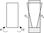
If the flange is considered as a fixed-ended beam of length b - t, the two forces F create a fixed end moment M;
M =


and thus the moment at mid-height of the web Mz can be found as follows [26]:

where:
Using the interaction criterion 
The limiting value of F is given when the left hand side of this criterion = 1.
If the length of the wall resisting F and M is h/2, given by a 45° dispersal in one direction, A = ht/2 and Wel,z = ht2/12. Substituting these values, introducing k = Mz /F, and rearranging, the limiting value becomes:
F =

where:
| nb |
=  |
and k is given by the expression for Mz/F above.
(c) Shear resistance
6.2.6(2)
The shear resistance is given by:
Vc,Rd =

where:
| Av |
is the shear area ( = A h / ( b + h )) |
| A |
is the area of the cross section |
| h |
is the overall depth |
| b |
is the overall width. |


 ≤ 1.0
≤ 1.0


 but kF ≤ 6


 ≤ ss + c


 as given in


