11.1 Bolt resistances
The types of bolts covered are:
- Classes 4.6, 8.8 and 10.9, as specified in BS EN ISO 4014[29], BS EN ISO 4016[31], BS EN ISO 4017[30] and BS EN ISO 4018[32], assembled with a nut conforming to BS EN ISO 4032[33] or BS EN ISO 4034[34]. Such bolts should be specified as also complying with BS EN 15048[21].
- Countersunk non-preloaded bolts as specified in BS 4933[28], assembled with a nut conforming to BS EN ISO 4032[33] or BS EN ISO 4034[34]. Such bolts should be specified as also complying with BS EN 15048[21] and, for grade 8.8 and grade 10.9, with the mechanical property requirements of BS EN ISO 898-1[35].
- Preloaded bolts as specified in BS EN 14399[20]. In the UK, either system HR bolts to BS EN 14399-3 or HRC bolts to EN 14399-10 should be used, with appropriate nuts and washers (including direct tension indicators to BS EN 14399-9, where required). Countersunk bolts to BS EN 14399-7 may alternatively be used. Bolts should be tightened in accordance with BS EN 1090-2[19].
(a) Non Preloaded Hexagon Head bolts and Countersunk bolts
For each grade:
- The first table gives the tensile stress area, the design tension resistance, the design shear resistance and the minimum thickness of ply passed through in order to avoid failure due to punching shear.
- The second table (and where applicable the third table) gives the design bearing resistance for the given bolt configurations.
(i) The values of the tensile stress area As are those given in the relevant product standard.
Table 3.4
(ii) The design tension resistance of a bolt is given by:
where:
| k2 |
= 0.63 for countersunk bolts |
| |
= 0.9 for other bolts |
| fub |
is the ultimate tensile strength of the bolt from the relevant product standard |
| As |
is the tensile stress area of the bolt |
| γM2 |
is the partial factor for bolts (γM2 = 1.25, as given in the National Annex). |
Table 3.4
(iii) The shear resistance of the bolt is given by:
where:
| αv |
= 0.6 |
for Classes 4.6 and 8.8 |
| |
= 0.5 |
for Class 10.9 |
| fub |
is the ultimate tensile strength of the bolt |
| As |
is the tensile stress area of the bolt. |
Table 3.4
(iv) The punching shear resistance is expressed in terms of the minimum thickness of the ply for which the design punching shear resistance would be equal to the design tension resistance. The value has been derived from the expression for the punching shear resistance given in BS EN 1993-1-8, table 3.4. The minimum thickness is given by:
where:
| Bp,Rd |
= Ft,Rd |
| Ft,Rd |
is the design tension resistance per bolt |
| dm |
has been taken as:
| Bolt |
dm (mm) |
| M 12 |
18.5 |
| M 16 |
23.2 |
| M 20 |
29.2 |
| M 24 |
35.0 |
| M 30 |
45.0 |
|
| fu |
is the ultimate tensile strength of the ply under the bolt head or nut |
| As |
is the tensile stress area of the bolt. |
(v) The bearing resistance of a bolt is given by:
Table 3.4
where:
| k1 |
 |
| e2 |
is the edge distance measured perpendicular to the direction of load transfer |
| p2 |
is the gauge measured perpendicular to the direction of load transfer |
| d0 |
is the hole diameter |
| αb |
 |
| fub |
is the ultimate tensile strength of the bolt |
| fu |
is the ultimate tensile strength of the ply passed through |
| e1 |
is the end distance measured in the direction of load transfer |
| p1 |
is the pitch measured in the direction of load transfer |
For countersunk bolts, the bearing resistance has been based on the thickness of the plate, minus half the depth of the countersinking. The depth of countersinking has been taken as half the bolt diameter, meaning the reduction in plate thickness is one quarter of the bolt diameter.
Bearing resistances have been calculated for the end distances, edge distances, pitch and gauge quoted in the tables.
The values of e2 in the second table are based on typical connections used in the UK and values of e2 in the third for Class 8.8 and 10.9 bolts table have been chosen to give increased resistances.
Clause 3.6.1(3) of BS EN 1993-1-8 states that where the threads do not comply with EN 1090 the relevant bolt resistances should be multiplied by a factor of 0.85.
Note 1 in Table 3.4 of BS EN 1993-1-8 gives the reduction factors that should to be applied to the bearing resistance for oversize holes and slotted holes.
(b) Preloaded hexagon head bolts and countersunk bolts at serviceability and ultimate limit states
(i) The tensile stress area, As, tension resistance, shear resistance, punching shear resistance and bearing resistance are calculated as given above.
When calculating the punching shear resistance for preloaded bolts, the following values of dm have been taken:
| Bolt |
dm (mm) |
| M 12 |
21.2 |
| M 16 |
27.0 |
| M 20 |
32.0 |
| M 24 |
41.0 |
| M 30 |
50.0 |
(ii) The tension resistance has been calculated as for non-preloaded bolts.
(iii) The bearing resistance has been calculated as for non-preloaded bolts.
BS EN 1993-1-8, 3.9.1(1)
(iv) The slip resistance of the bolt is given by:
 |
at SLS |
 |
at ULS |
Table 3.6
Table 3.7
where:
| ks |
is taken as 1.0 |
| n |
is the number of friction surfaces |
| μ |
is the slip factor |
Slip resistances for a range of slip factors, μ are provided. Designers should ensure the value selected is appropriate for the surfaces to be fastened, or should calculate revised resistances.
| Fp,C |
= 0.7 fub As is the preloading force |
| γM3 |
is the partial factor for slip resistance (According to the National Annex, γM3 = 1.25 at ultimate limit state, and γM3,ser = 1.1 at serviceability limit state). |
Tables are provided for connections which are non-slip at the serviceability state and those that are non-slip at the ultimate limit state. In both cases, according to BS EN 1993-1-8, 3.4.1, bearing resistance must be checked, and resistance values are provided for this purpose.
Note that for connections which are non-slip at the serviceability limit state, the slip resistance must be equal to or greater than the design force due to the SLS values of actions (i.e. not the design force due to ULS actions).
11.2 Welds
BS EN 1993-1-8
4.5.3.3
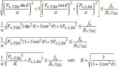
Design resistances of fillet welds per unit length are tabulated. The design resistance of fillet welds will be sufficient if the following criteria are both satisfied:
 |
and |
 |
Eq (4.1) |
Each of these components of the stress in the weld can be expressed in terms of the longitudinal and transverse resistance of the weld per unit length as follows:
Therefore:
BS EN 1993-1-8 4.5.3.3(2)
From this equation, taking each of the components in turn as zero, the following expressions can be derived for the longitudinal and the transverse resistances of welds:
| Design weld resistance, longitudinal: |
Fw,L,Rd = fvw,d a |
| Design weld resistance, transverse: |
Fw,T,Rd = KFw,L,Rd |
BS EN 1993-1-8 4.5.3.3(3)
where:
| fvw,d |
is the design shear strength of the weld  |
| fu |
= 410 N/mm2 for S275 |
| |
= 470 N/mm2 for S355 |
| |
= 520 N/mm2 for S420 |
This value is valid for thicknesses up to 100 mm |
| |
= 550 N/mm2 for S460 |
This value is valid for thicknesses up to 100 mm |
BS EN 1993-1-8 Table 4.1
| βw |
= 0.85 for S275 |
| |
= 0.9 for S355 |
| |
= 1.0 for S420 |
| |
= 1.0 for S460 |
| γM2 |
is the partial factor for the resistance of welds (γM2 = 1.25 according to the National Annex) |
| a |
is the throat thickness of the fillet weld |
| K |
 |
The above expression for transverse weld resistance is valid where the plates are at 90° and therefore θ = 45° and K = 1.225.