7.1Tension members: Single angles
EN 1993‑1‑1
6.2.3
For angles in tension connected through one leg, BS EN 1993-1-1, 6.2.3(5) refers to BS EN 1993-1-8, 3.10.3. However the Eurocode does not cover the case of more than one bolt in the direction perpendicular to the applied load. Therefore the resistance has been calculated using expressions from BS 5950-1 for angles bolted and welded through one leg. The resistance is independent of the number of bolts along the angle and their spacing. Tables only give values for the cross-sectional check; see AD351[17] for more information.
6.2.3(2)
The value of the design resistance to tension Nt,Rd has been calculated as follows:
where:
| Aeq |
is the equivalent tension area of the angle |
| fy |
is the yield strength |
| γM0 |
is the partial factor for resistance of cross sections (γM0 = 1.0, as given in the National Annex). |
The equivalent tension area of the section Aeq is given by:
For bolted sections:
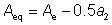
For welded sections:
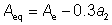
where:
| Ae |
= ae1 + ae2 |
but Ae ≤ 1.2 (an1 + an2) |
| ae1 |
= Ke an1 |
but ae1 ≤ a1 |
| ae2 |
= Ke an2 |
but ae2 ≤ a2 |
| Ke |
= 1.2 |
for grade S275 |
| |
= 1.1 |
for grade S355 |
| an1 |
= a1 - nbolts d0t |
| a1 |
= h x t if the long leg is connected |
| |
= b x t if the short leg is connected |
| nbolts |
is the number of bolts across the angle |
| d0 |
is the diameter of the hole |
| an2 |
= a2 |
| a2 |
= A – a1 |
| A |
is the gross area of a single angle. |
Note: A block tearing check (BS EN 1993-1-8, 3.10.2) is also required for tension members. However, block tearing resistances have not been tabulated, as there are too many variables in the possible bolt arrangements.
